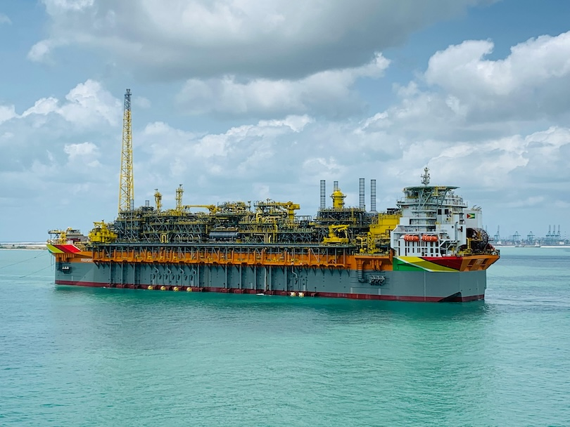
Floating Production, Storage and Offloading (FPSO) units are offshore production facilities built on floating hulls (most commonly ship‑shaped monohulls) that receive multiphase well fluids via risers, separate the stream into oil, gas and water, treat each stream to export or disposal specifications, store stabilised crude in cargo tanks, and periodically offload it to export tankers. They are widely used where fixed platforms are uneconomic or impractical (deep water, remote locations, or limited pipeline/export infrastructure) and are often regarded as the most adaptable of floating production concepts.
From an engineering viewpoint, the FPSO vessel is best understood as four tightly coupled systems:
- topsides (process plant, utilities, control/safety systems)
- hull (buoyancy, global strength, storage, ballast and marine systems)
- station‑keeping (spread mooring, turret mooring, and/or thruster assistance)
- fluid transfer interfaces (risers/umbilicals in, export/offloading out, plus swivels where the hull weathervanes around a turret)
Conversions of trading tankers typically aim to compress schedule and-sometimes-capital cost by reusing an existing hull; purpose‑built new-builds can be optimised for long on‑station life, weight distribution, turret integration, fatigue, and harsh met-ocean conditions, at the cost of longer delivery and higher up‑front commitment. A classic industry paper (1993) already framed the decision primarily as a trade‑off among time to first oil, cost, and required on‑station life; those drivers still dominate, though modern topsides scope and safety/regulatory requirements generally push absolute costs far above early‑era figures.
Operationally, the production “core loop” is:
- well fluids arrive
- staged separation
- oil stabilisation
- water treatment/injection/disposal
- gas treatment and compression (for fuel, export, gas lift or reinjection)
- crude storage
- offloading
The “marine loop” is: maintain station within allowable offsets (to protect risers and subsea infrastructure) → manage simultaneous operations (SIMOPS) such as offloading and maintenance → maintain barriers against hydrocarbon release and escalation.
Safety performance data are not usually published specifically for “FPSOs only”; instead, FPSOs sit within broader upstream/offshore statistics.
In the latest IOGP safety indicator dataset (2024), 32 company+contractor fatalities were reported across participating member company operations (17 onshore, 15 offshore), with an overall Fatal Accident Rate (FAR) of 0.77 per 100 million hours; the offshore FAR was higher than the prior year in that dataset. Marine contracting benchmarks (IMCA) for 2024 show an offshore TRIR of 1.38 and “line of fire” as the leading cause of lost‑time injuries-hazard categories that map directly to FPSO vessel high‑risk activities (lifting, mooring/offloading, rotating machinery, pressurised systems).
A widely cited “largest” FPSO depends on the metric. A recent 2026 technical review identifies Egina as the fleet record holder for crude storage capacity (2.3 million bbl) and possibly topsides weight around 2025; operator materials list 200,000 b/d production capacity and 2.3 million bbl storage.
Definition and purpose of FPSO Vessel
An FPSO is a floating facility that receives reservoir fluids from subsea wells through flowlines/risers and separates the multiphase stream into crude oil, gas, produced water and impurities using onboard processing equipment (“topsides”). Stabilised crude is stored in the vessel’s cargo tanks and periodically offloaded to export tankers; gas is treated (e.g., dehydration) and used as fuel, exported, re-injected, or used for gas lift-typically requiring compression. Produced water is treated for overboard discharge or reinjection (often after further conditioning and/or blending with seawater for injection schemes).
A useful adjacent concept is the FSO (Floating Storage and Offloading): it is primarily a storage and export unit that receives (typically) pre‑treated oil from another facility and offloads to tankers, with markedly reduced process scope compared with an FPSO. This distinction matters operationally because it shifts complexity away from separation/treatment and toward storage management and marine/offloading operations.
FPSOs are favoured when they provide lower whole‑life cost or lower project risk than fixed platforms or pipeline‑heavy schemes-particularly in deep water or remote regions where pipeline export is unavailable or uneconomic, and where redeployment at field end provides additional value.
FPSO Vessel – Engineering Architecture and Main Systems
Structural parts and their roles
Most FPSOs are ship‑shaped monohulls-either
- converted tankers
- purpose‑built new-builds
but other hull forms exist (including cylindrical concepts) and are treated in class guidance as alternate unit types.
Key physical subsystems and what they do:
- Hull/ marine systems (the “platform”): provides buoyancy and global strength; hosts ballast systems for stability/trim; houses cargo tanks for crude storage; contains cargo piping, pumps and inert gas arrangements needed for safe storage and transfer.
- Topsides / modules (the “plant”): process train(s) for separation, oil treatment, gas treatment/compression, produced water treatment, chemical injection, power generation and utilities; includes control and safety systems (process shutdown, fire & gas detection, etc.) whose safety relevance is explicitly recognised in floating‑production‑unit rules/guidance.
- Station‑keeping system (the “foundation”): keeps the vessel within allowable offsets and headings for design environmental conditions and for riser/umbilical excursion limits. Main categories include spread mooring, turret mooring (internal or external), disconnectable systems, and thruster‑assisted arrangements.
- Risers/umbilicals/flowlines (the “subsea interface”): bring well fluids to topsides and return injection or export streams; can be flexible or rigid, and turret‑moored units typically require a swivel stack / multipath swivel to pass fluids and services between fixed risers and a rotating hull.
- Offloading/export systems (the “sales interface”): transfer stabilised crude from storage to export tankers-often via stern tandem systems and/or an offshore loading/offloading buoy; may also include gas export lines where applicable.
Turret Versus Spread‑Moored Concepts
The turret mooring system is a single‑point mooring arrangement that can be installed internally (within the hull) or externally. Its defining operational advantage is weathervaning: the hull can rotate freely around the turret to align with wind/wave/current, which tends to reduce environmental loads and motions and can improve uptime and offloading availability.

A spread‑moored FPSO is held by multiple mooring lines attached at multiple points; this generally fixes the heading (or strongly constrains it), which can be advantageous where a fixed orientation is desired (e.g., layout constraints), but can increase loads if environmental directions vary widely. Spread moorings and catenary moorings are explicitly defined and treated in classification mooring guidance for floating production units.
Conversion versus new-build: project delivery, timelines, cost
Engineering Logic Behind The Choice
A long‑standing industry framing is that the conversion vs new-build decision is largely governed by (I) time and cost to deliver and (II) required life on station-with additional sensitivity to environment and regulatory requirements. The classic 1993 paper emphasises that used tankers are considered primarily for time and cost savings, but that conversion cost cannot be estimated reliably without ship‑specific inspections and that upgrades/coatings/repairs can erode the expected advantage.
A key structural‑integrity caution from that same source is that if a field is expected to produce for more than roughly 15 years, an older converted tanker may not have sufficient remaining primary structural life without substantial renewal; corrosion and fatigue evaluation become central.
Classification guidance explicitly treats both new builds and conversions as valid pathways, but expects design and construction to meet offshore unit requirements for the intended service (including on‑site design environmental conditions and mooring/riser loads).
Typical Process Steps
Because each FPSO is bespoke to its reservoir fluids, export philosophy, and metocean environment, detailed “step lists” vary by project. A robust, engineering‑typical workflow looks like this:
Conversion
- candidate selection and due diligence (structural surveys, corrosion/fatigue screening, tank condition, machinery)
- concept/FEED for turret/spread mooring, risers, topsides layout and weight control
- tanker purchase/charter and regulatory/class plan approval
- dry-dock and steel renewal/coating upgrades
- major structural modifications (deck strengthening, turret integration if required, module supports)
- marine systems upgrades (power distribution, ballast, fire protection, accommodation/HVAC)
- topsides module fabrication and integration
- commissioning (yard and offshore)
- tow‑out/hook‑up and start‑up
The need for vessel surveys and refurbishment scoping before firm cost/time estimates is emphasised in the conversion literature.
New-build
- concept/FEED with hull form optimisation (global strength, fatigue, storage, turret integration), compliance planning and class approval
- long‑lead procurement (turret, swivel, compressors, power generation)
- hull construction
- parallel topsides module fabrication
- integration (often at a dedicated integration yard)
- commissioning
- sail‑away/tow‑out + hook‑up/start‑up
Newbuild advantages are primarily in optimised design margins and predictability for a specified on‑station life.
Timelines
A frequently cited (historical) rule of thumb is: a suitable conversion can be materially quicker than a newbuild – conversions “require about one year” while designing and constructing a new-build “may take two years and sometimes longer” (noting shipyard slot availability).
Modern deepwater developments often show multi‑year end‑to‑end schedules (from project sanction through commissioning). For example, the Egina it was a five years development, indicating that for large, integrated developments, the FPSO schedule is embedded in a broader project critical path (subsea wells, risers, integration, commissioning).
Cost Ranges
A historical cost illustration (1993) provides a line‑item estimate for a 1,000,000 bbl FSO comparing new construction versus conversion, showing total ranges of roughly US$43.5–49.9 million (new) versus US$16.2–24.0 million (conversion), plus tanker purchase price cited as US$8-16 million-figures that are not representative of modern high‑capacity FPSOs with heavy topsides, but still useful to show how cost components were framed (hull structure, machinery, coatings, safety systems, class, etc.).
A modern new-build datapoint: the integration yard’s announcement for Egina cites a ~US$3.0 billion turnkey order for engineering/procurement/construction/installation/commissioning of the FPSO, while a Nigerian regulator‑adjacent release references a US$16 billion development budget for the overall Egina project (which includes far more than the FPSO itself).
Comparison table: conversion versus new-build

Production Process And Operations
Step-by-Step Production Processing on an FPSO
A canonical FPSO process concept (with project‑specific variations) proceeds as follows:
- Inflow from subsea wells: multiphase well fluids (oil/gas/water/sand) arrive via risers and flowlines to the topsides inlet; slug handling and inlet manifolding distribute flow to separation trains.
- Primary separation (often staged): gravity separation in 2‑phase or 3‑phase separators (commonly HP → MP → LP trains) splits bulk gas, oil and water. Recent FPSO topsides trends include compact separation technologies to reduce weight and footprint, but the fundamental objective remains clean phase separation into exportable/processable streams.
- Oil treatment and stabilisation: crude is treated to meet export requirements and stabilised to control vapour pressure, then routed to storage tanks in the hull.
- Gas treatment and compression: separated gas is dehydrated and then routed as fuel gas for power generation/utilities, for gas lift, for reinjection, or to a gas export pipeline—each typically requiring compression.
- Produced water treatment / disposal or injection: water separated from the wellstream is treated to reduce residual oil before discharge, or conditioned for reinjection (often via dedicated injection systems; some schemes blend produced water with seawater). The regulatory treatment of produced-water discharge is typically governed by national/regional offshore rules rather than MARPOL Annex I for the production plant discharge.
- Storage management: crude accumulates in cargo tanks; inerting and cargo management maintain safe tank atmospheres and transfer capability.
- Offloading/export: crude is pumped to export tankers via the FPSO’s offloading system; export philosophy may be tanker offloading, pipeline export, and/or combined arrangements depending on field infrastructure.
In floating production unit guidance, the topsides process scope is usually treated as beginning at the first well‑fluid inlet flange above the water level and ending at the storage tank interface—an important “systems engineering” clarity point for design responsibility splits among subsea, turret, topsides and hull teams.
Example: High-Capacity Water And Gas Treatment Packages (Egina)
Public vendor documentation for Egina illustrates the scale of treatment modules on large FPSOs: produced water treatment designed around 2,090 m³/h to 15 mg/L oil‑in‑water discharge, and glycol dehydration/regeneration for ~180 MMSCFD wet gas (example process package scope), alongside sand handling packages. This is an example of how separation is not “just separators”; it is a full treatment chain sized to both throughput and environmental specifications.
Offloading Operations And Methods
Offloading methods used with FPSOs
Offloading arrangements vary by site conditions, export strategy, and tanker fleet. Common approaches include:
- Tandem offloading to shuttle tanker: the shuttle tanker approaches astern (or at a controlled offset), connects to an offshore loading terminal/buoy or directly to the FPSO via hose arrangements, then receives crude through a bow loading or manifold connection. Tandem offloading and shuttle tanker requirements are described in industry “offshore loading shuttle tanker” guidelines, including bow loading system architecture.
- Side‑by‑side (SBS): the export tanker comes alongside the FPSO for transfer (risk profile is sensitive to metocean, fendering, and relative motion control). Detailed, universally applicable public procedural requirements are often operator‑specific; therefore, step details may be unspecified in public sources.
- FSO with shuttle tanker export: conceptually similar marine transfer, but with reduced topsides processing on the floating unit (FSO).
- DP‑enabled approaches: DP is frequently used on shuttle tankers and offshore support vessels during loading/offloading and station‑keeping support operations. The IMO DP guidelines were developed to reduce risk to personnel, vessels, subsea installations and the environment during DP operations.
Operational steps for tandem offloading (typical)
A practical tandem offloading sequence (generalised from shuttle‑tanker guidance, noting that operators add field‑specific barriers and checklists):
- Pre‑arrival planning: confirm weather window and operating limits; verify systems readiness (cargo transfer, ESD/ASD logic, telemetry); confirm manning and communications protocols within the safety zone.
- Approach and positioning: shuttle tanker establishes DP/position monitoring consistent with the applicable DP guidance and field requirements; performs approach under defined speed and exclusion‑zone rules.
- Connection: connect hawser and cargo hose to the tanker’s bow loading system/manifold as applicable; establish the control/telemetry link for emergency shut‑down (industry guidance distinguishes operating modes and signal links—e.g., “Blue Line” for offloading mode in one guideline).
- Transfer: start pumping; monitor flowrates, pressures, and hose/hawser tensions; maintain DP and heading/offset limits; manage vapour handling and tank gauging.
- Completion and line management: stop transfer per procedure; flush/purge lines as required; depressurise and disconnect hose/hawser; verify ESD system state and log key parameters.
- Departure: shuttle tanker clears the zone; FPSO returns to normal marine configuration; post‑operation checks and reporting.
Where the offloading system includes dedicated offloading lines to a buoy/terminal, contractor documentation for Egina notes large‑bore flexible offloading lines connecting an FPSO to an offloading buoy, illustrating a common deepwater export architecture coupling subsea/turret/offloading interfaces.
Comparison table: offloading methods

Station-Keeping, Turrets, Anchors, Seabed Integrity
Station-keeping objectives and design checks
Station‑keeping is fundamentally about keeping the floating unit’s offset and heading within allowable envelopes for the riser/umbilical system under defined environmental conditions (design environmental condition, design operating condition, etc.). Class mooring guidance formalises these conditions and requires analysis of environmental loading, vessel response, mooring line tensions and (where applicable) anchor holding capacity.
Anchor and mooring system components
Classification mooring guidance for floating installations identifies the main mooring components as mooring lines (chain, wire, synthetic rope or combinations), winching equipment and anchoring systems. Anchor/foundation types explicitly within scope include drag embedment anchors, pile anchors (driven/jetted/drilled and grouted), dynamically installed piles, suction piles/caissons, gravity anchors, plate anchors (including suction‑embedded plate anchors), and related hardware.
Engineering implications (high‑level)
- Drag embedment anchors are common for catenary systems where horizontal holding dominates.
- Suction piles/caissons and pile anchors support higher vertical components (taut/semi‑taut systems), but require geotechnical capacity checks and installation analyses (penetration, retrieval considerations).
- Fatigue life is treated explicitly; for example, guidance for pile anchors can require design fatigue life margins relative to intended service.
Turret systems and disconnect-ability
Turret mooring is treated as one category of station‑keeping and can be internal or external. In class terminology, “Disconnectable” indicates the presence of propulsion and means of disengaging the installation from mooring and risers so the unit can ride out severe weather or seek refuge under its own power for a specified design environmental condition.
Recent academic work also highlights active heading control strategies (thruster‑assisted mooring/DP‑assisted mooring) as a way to reduce mooring tensions and improve station‑keeping performance-reinforcing the operational reality that many FPSOs are not purely passive moorings, but integrated control‑structure systems.
Ensuring seabed integrity
“Seabed integrity” for FPSO station‑keeping is primarily ensured through:
- site investigation (bathymetry, obstructions, soil stratigraphy)
- geotechnical design (anchor holding capacity and foundation stability)
- installation analysis and QA/QC (proof loads, installation records, as‑built verification)
- in‑service inspection/monitoring (periodic surveys, tension/condition monitoring)
Two explicit examples from primary guidance illustrate these expectations:
- Floating production guidance requires submission of a site plan indicating bathymetric features, obstructions, and other sea‑floor characteristics for import/export system planning-an example of formalising seabed understanding as an engineering deliverable.
- Mooring guidance requires geotechnical holding capacity and structural analyses for anchors such as suction piles, plus installation analyses to show penetrability and potential retrieval, and it specifies documentation and survey regimes for installed systems.
Safety For Personnel, Lifecycle, And Largest FPSO Case Study
Main hazards on FPSOs
FPSOs combine process‑plant hazards with marine/offloading hazards. The dominant personnel risk exposures typically include:
- Hydrocarbon release → fire/explosion escalation (process equipment, piping, vents, offloading hoses)
- Line‑of‑fire/ stored‑energy (pressurised systems, rotating equipment, mooring lines, lifting operations)
- Dropped objects/ lifting and crane operations (module maintenance, cargo handling)
- Marine interface events (collision/contact during offloading, loss of position, hose rupture)
- Helicopter and transfer risks (personnel movement to/from offshore installations; requirements are typically governed by national aviation and offshore regulations-often treated as a major hazard category operationally)
A useful cross‑industry indicator: in IMCA’s 2024 safety statistics, “line of fire” is identified as the most common cause of lost‑time injuries (52% of LTIs in that dataset), with slips/trips second-hazard categories directly relevant to FPSO deck operations, lifting, and marine transfer tasks.
Typical safety systems and barrier measures
Floating production unit guidance embeds conventional offshore barrier philosophy: prevent loss of containment; detect abnormal events rapidly; isolate and depressurise; suppress and manage escalation; protect personnel via layout, hazardous area classification, and escape/survival systems.
Examples explicitly present in offshore/floating production guidance include:
- Hazardous area classification requirements and segregation principles for spaces where gas dispersion may not occur.
- Gas detection and alarm provisions (guidance requires gas detectors in specified areas and alarms in control locations).
- Ventilation provisions for machinery and enclosed spaces, including non‑sparking ventilation in appropriate contexts.
- Mooring/offloading procedural barriers, including tested Bow Loading Systems, telemetry/ESD links, data logging, and DP testing aligned with IMO DP guidance for shuttle tanker operations.
Incident statistics and trends (contextualised for FPSOs)
Public statistics are generally not FPSO‑only; nevertheless, they provide a rigorous baseline for the risk environment FPSOs operate within.
In the IOGP 2024 safety indicators dataset (occupational safety across reporting member company operations):
- 32 company+contractor fatalities were reported for 2024 (17 onshore, 15 offshore), occurring in 21 separate incidents.
- The overall FAR was 0.77 (6% lower than 2023’s 0.82); however, the dataset’s offshore FAR was 1.31 in 2024, higher than the prior year’s offshore FAR in that dataset.
- The fatal incident rate (FIR) is reported as 0.50 overall for 2024 (down slightly from 0.52), with offshore FIR higher than the prior year in that dataset.
- For production activities, the dataset reports overall (company+contractor) TRIR ≈ 0.85 and LTIR ≈ 0.26 (per million hours) for 2024.
For marine contracting (IMCA 2024):
- Total TRIR 1.10 and offshore TRIR 1.38; LTIFR offshore 0.35; 3 fatalities reported (2 offshore, 1 onshore) in that dataset.
Regulators such as the UK’s offshore safety authority publish annual offshore statistics and hydrocarbon release reporting summaries, providing additional regional trend context for threats like hydrocarbon releases (a core major accident precursor).
Largest FPSO Case Study
Case study vessel (largest by crude storage capacity): Egina FPSO
- Name: Egina FPSO (Egina field development)
- Operator/ “owner” context (field partnership): TotalEnergies is listed as operator, with partners including NNPC, CNOOC, SAPETRO, and Prime 130 (partnership composition as stated by the operator).
- Location: offshore Nigeria (block formerly OML 130 / water depth ~1,400–1,700 m reported by operator).
- Daily production capacity: 200,000 b/d (operator‑stated production capacity at plateau).
- Crude storage capacity: 2.3 million barrels (operator‑stated; also identified in a 2026 technical review as fleet record for crude storage capacity)
- POB (people on board): over 200 persons; because this figure is not consistently stated in operator publications, it should be treated as indicative unless validated against the project’s certified accommodation documentation.
- Notable operational feature: described by the operator as Nigeria’s first “zero routine flaring” oil project, enabled by a gas compression system transporting associated gas to the Nigeria LNG terminal near Port Harcourt.

Typical FPSO Service Life And Factors Affecting Life
Design lives are commonly multi‑decade, but the limiting factors are dominated by fatigue/corrosion of the hull structure, integrity of mooring/riser systems, turret bearing/swivel wear (where applicable), and topsides obsolescence or scope change as reservoir conditions evolve.
Concrete examples from public sources:
- Egina is stated as designed for 25 years of operations in a Nigerian industry/regulatory‑adjacent release.
- Vendor documentation for Egina’s mooring equipment references a design life of 28 years for a permanent mooring system (equipment‑scope statement).
- Conversion guidance stresses that corrosion and fatigue evaluation are decisive and that long field life can render older tanker hulls unsuitable without major renewal.
- A 2026 review highlights that some FPSOs have been redeployed repeatedly and operated for 40+ years (fleet history example), showing that service life is not solely “design life” but also a function of refurbishment and redeployment economics.
Decommissioning considerations
FPSO end‑of‑life pathways typically include: redeployment/refurbishment, conversion to other service, or dismantling/recycling. Decommissioning engineering must consider hydrocarbon inventory management, tank cleaning/inerting, removal of moorings/risers, and compliance with ship recycling regimes when the hull enters recycling streams.
A key regulatory development for recycling is that the Hong Kong International Convention for the Safe and Environmentally Sound Recycling of Ships entered into force on 26 June 2025, establishing internationally binding requirements intended to improve safety and environmental performance in ship recycling. This is directly relevant when FPSO hulls are treated as ships for recycling purposes.
Are you looking for affiliate partnerships, marketing, professional collaboration, let’s get in touch and discuss. Leave your request on the contact form or contact us directly at [email protected].
As well if you are interested on getting a copy of the 2026 Edition – Guideline For Thorough Incidents Reporting and Investigation, SUBSCRIBE to HSE Smart Solutions and you will get it by email. First 100 subscriptions will get a free copy.
Leave a Reply